Instructions and precautions for using photoelectric switches
 22 Nov 2024 click : 1028
Photoelectric switch is the abbreviation of photoelectric proximity switch, which uses the obstruction or reflection of the light beam by the detected object to connect the circuit through a synchronous circuit, thereby detecting the presence or absence of the object. Objects are not limited to metals, and all objects that can reflect light (or obstruct light) can be detected.
According to the detection method, it can be divided into diffuse, reflective, mirror reflective, slot type photoelectric switches, and fiber optic photoelectric switches;
Opposite type photoelectric switch

Composed of a transmitter and a receiver, structurally separated from each other, a switch signal change occurs when the beam is interrupted. Typically, photoelectric switches located on the same axis can be separated from each other by up to 50 meters.
Features: Identify opaque reflective objects; The effective distance is large because the light beam only crosses the sensing distance once; Not easily disturbed, can be reliably and appropriately used in the wild or dusty environment; The consumption of the device is high, and cables must be laid for both units.
Diffuse reflection photoelectric switch

Diffuse reflection type refers to the phenomenon where the target undergoes diffuse reflection when the switch emits a beam of light; The transmitter and receiver form a single standard component, and when there is enough combined light returning to the receiver, the switch state changes, with a typical operating distance of up to 3 meters.
Features: The effective range is determined by the target's reflective ability, surface properties, and color; Small assembly costs, when the switch is composed of a single component, can usually achieve rough positioning; Using background suppression function to adjust measurement distance; Sensitive to dust on the target and sensitive to changes in the target's reflectivity.
Mirror reflection photoelectric switch

Mirror reflection is a standard configuration consisting of a transmitter and a receiver. The beam emitted from the transmitter is reflected by the opposite mirror and returns to the receiver. When the beam is interrupted, a switch signal is generated. The passage time of light is twice the signal duration, and the effective range is from 0.1 meters to 20 meters.
Features: Distinguish between opaque and non reflective objects; By utilizing reflective mirror components, a high effective distance range is formed; Not easily disturbed, it can be reliably and appropriately used in the wild or dusty environment.
Slotted photoelectric switch

Slot type photoelectric switches are usually standard U-shaped structures, with the transmitter and receiver located on either side of the U-shaped slot and forming an optical axis. When the detected object passes through the U-shaped slot and blocks the optical axis, the photoelectric switch generates a detected switch signal. Slot type photoelectric switches are relatively safe and reliable, suitable for detecting high-speed changes and distinguishing between transparent and semi transparent objects.
Fiber optic photoelectric switch

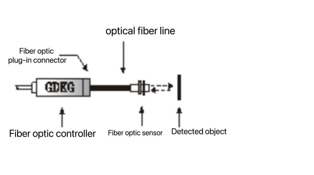
Fiber optic photoelectric switches use plastic or glass fiber optic sensors to guide light, in order to detect objects that are not in close proximity. Fiber optic sensors are usually divided into reflective and diffuse reflective types.
Precautions and measures
(1) Optoelectronic switches can be used in various applications. In addition, when using photoelectric switches, attention should also be paid to environmental conditions to ensure that the photoelectric switches can work normally and reliably.
(2) Strong light source: The photoelectric switch can generally work stably when the ambient illumination is high. But avoid aligning the sensor's optical axis directly with strong light sources such as sunlight and incandescent bulbs. When the angle between the optical axis of the sensor (receiver) and the strong light source cannot be changed, a light shielding plate or a long light shielding tube can be installed around the top of the sensor.
(3) Mutual interference: When several groups of parallel infrared photoelectric switches are installed in close proximity, adjacent groups and mutual interference should be prevented. The most effective way to prevent this interference is to cross set the projector and receiver, and when there are more than two groups, the group spacing should be widened. Different frequency models can also be used.
(4) Mirror angle: When the object being tested has a glossy surface or encounters a smooth metal surface, the reflectivity is generally high, which has an approximate mirror effect. At this time, the projector should be installed at an angle of 10-20 ° with the object being tested, so that its optical axis is not perpendicular to the object being tested, thereby preventing misoperation.
(5) Background object: When using a reflective diffusion type projector or receiver, sometimes due to the proximity of the detected object to the background object, the photoelectric switch or the background being smooth or other objects with high reflectivity, the photoelectric switch may not be able to detect stably. Therefore, distance limited projectors and receivers can be used instead, or methods such as keeping away from the background, removing the background, painting the background black without light, or trying to make the background rough and dark can be used to eliminate it.
(6) Table influence: When the projector and receiver are installed close to the table, there may be some reflected light beams from the table shining on the receiver, causing unstable operation. This can be achieved by placing the light receiver and projector at a certain distance from the table and installing a shading plate.
It is strictly prohibited to use chemical substances such as diluents to avoid damaging the plastic mirror. The wiring of high-voltage lines, power lines, and photoelectric sensors should not be placed in the same wiring conduit or trunking, otherwise it may cause (sometimes) misoperation or damage of photoelectric switches due to induction. Therefore, in principle, they should be wired separately.


